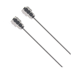
RCS086L-UMUM-L is a RCS086L assembly with 2.4mm male on one end and 2.4mm male on the other, specified from DC to 50 GHz. The headline figures are a VSWR of 1.35:1 maximum and an insertion loss of 5.63 dB, all specified across the full DC to 50 GHz band rather than at spot frequencies. With a pin at each end, the part mates two sockets; check both ports are female before ordering. Both ends are terminated and the assembly is tested as a unit, so its loss and match are known before it is installed. It is built in the Precision tier, held to tight tolerances at the mating plane and on the centre contact.
Specifications
- Interface A: 2.4mm male
- Interface B: 2.4mm male
- Frequency: DC to 50 GHz
- Impedance: 50 ohm
- VSWR: 1.35:1 maximum
- Insertion loss: 5.63 dB/m maximum at 50 GHz
- Body: passivated stainless steel
- Centre contact: gold-plated beryllium copper centre contact
- Weight: 0.15 kg
- Grade: Precision
Where it is used
It replaces hand-fitted connector-and-cable combinations with a tested, labelled part that can be reordered by number. Rack builders use it for the permanent RF runs inside an enclosure, where a cable is installed and then forgotten.
Because the assembly is tested as a unit, the loss and match you design against are the numbers the part actually delivers, not the sum of catalogue figures.
Q-band operation rewards the precision tiers: the same interface in a standard build would show a visibly worse return loss here.
Compatibility and mating
Mating is limited to 2.4mm and 1.85mm parts. The small centre pin and air dielectric reward careful handling: gauge or inspect the interface if a measurement suddenly looks worse than it should.
Mating is by the book: clean the interfaces, align the keys, torque to the figure for that series. The cable side needs support so the connector does not carry the run’s weight.
Check the interface with a gauge after any drop. A part that has been dropped usually looks fine and measures badly.
Ordering
Order by the part number as listed: the code encodes the interface pair, the gender at each end and the body style, so a different suffix is a different part rather than a variant of this one.
Length is quoted per piece and the assembly is built to it; state the finished length, not the cable cut length, because the connectors consume part of the run.
Frequently asked questions
Why does the loss figure have a per-metre basis?
Cable loss scales with length, so the datasheet quotes dB per metre at a stated frequency. Multiply by your length and add the connector losses.
Does length change the phase?
Yes, phase scales with electrical length. If phase matters, order to an electrical length tolerance rather than a mechanical one.
How do I order a length?
Give the finished length per piece and the quantity. The assembly is cut, terminated and tested to that length, and the length is marked on the jacket.
How is it tested?
Each assembly is continuity-checked and loss-tested, and the results trace to the part number and length marked on it.
What bend radius should I respect?
The datasheet gives the minimum for the cable. Tighter bends raise loss and, over time, shift phase.



Reviews
There are no reviews yet.