Most cable assemblies are chosen by their connectors. An engineer needs an SMA male to SMA male jumper, picks a length, and the cable inside — .086 semi-rigid, RG-316, low-loss phase-stable, armored — is treated as packaging rather than as a component. That works up to about 18 GHz, where the connector still dominates the measurement. Above 18 GHz the cable becomes the largest single source of error in the setup, and it does so in three ways that have nothing to do with the datasheet headline: loss per metre, phase drift, and the transition where the cable meets the connector.
This guide is about choosing the cable, not the connector. It covers the four numbers worth comparing, what each cable family actually costs you at 40 GHz, and the two failure modes — a moving reference plane and a junction that was never designed for the frequency — that turn a good VNA into an instrument that measures its own test lead.
The Four Numbers That Decide a Cable Assembly
A cable assembly datasheet is long, but four numbers do almost all of the work. Everything else is a consequence of them.
- Insertion loss at the top of the band, per metre. Not at 1 GHz, and not “typical”. Loss rises roughly with the square root of frequency, so a cable quoted at 0.5 dB/m at 1 GHz is closer to 3 dB/m at 40 GHz — six times worse, which for a 1 m run means half your dynamic range disappears.
- Phase drift with temperature and with handling. This is the number that decides whether a measurement setup is repeatable. It is quoted in ppm of electrical length per °C, or in degrees per GHz per °C. If the datasheet does not quote it at all, the cable is not intended for phase-sensitive work.
- Return loss, and its stability over mating cycles. A cable assembly with 20 dB return loss that stays at 20 dB after being reconnected is worth more than one at 26 dB that wanders by 6 dB each time you touch it.
- Minimum bend radius, static and dynamic. The number that gets ignored until a cable is routed through a chassis and the loss jumps.
Our cable assembly range is organised around exactly these distinctions rather than around connector combinations, because two assemblies with identical connectors can differ by 6 dB/m at 40 GHz.
What Each Cable Family Actually Costs You
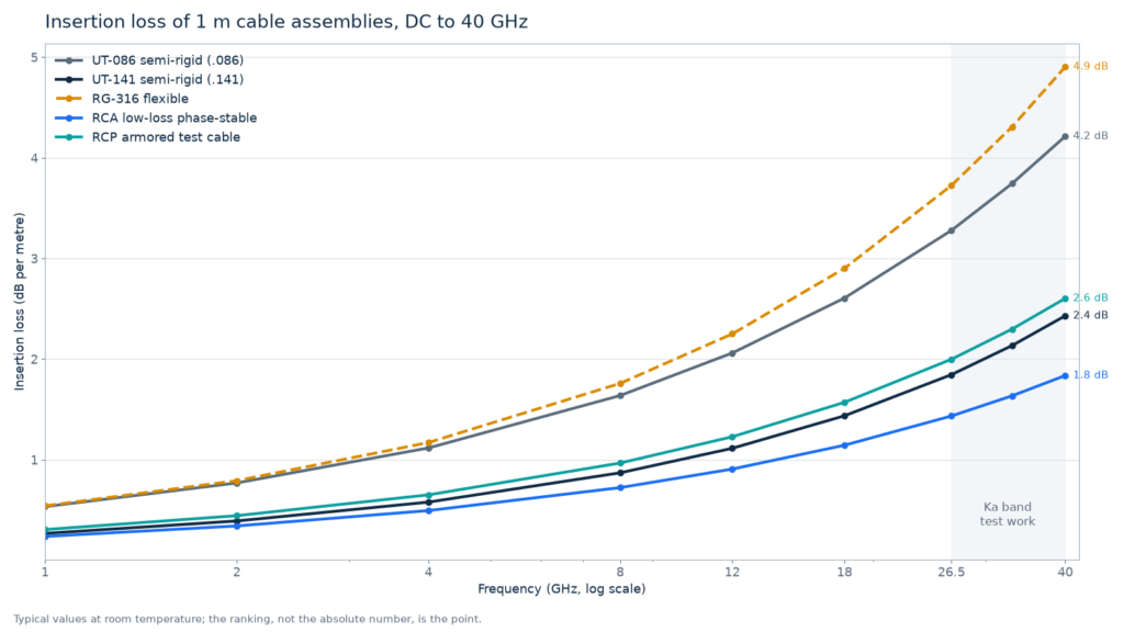
The chart below compares five families at 1 m, using typical room-temperature figures. The ranking matters more than the absolute values, which move by ±20 % between manufacturers and with connector quality.

| Family | Loss at 18 GHz | Loss at 40 GHz | Phase vs temperature | Use it for |
|---|---|---|---|---|
| UT-086 semi-rigid | ≈ 2.6 dB/m | ≈ 4.2 dB/m | 25–30 ppm/°C | Short fixed runs inside an enclosure |
| UT-141 semi-rigid | ≈ 1.6 dB/m | ≈ 2.5 dB/m | 25–30 ppm/°C | Module-to-module links, phase-stable by construction |
| RG-316 flexible | ≈ 2.9 dB/m | ≈ 4.9 dB/m | several hundred ppm/°C | DC and low-frequency hookup, never phase-sensitive work |
| RCA low-loss phase-stable | ≈ 1.2 dB/m | ≈ 1.8 dB/m | 40–50 ppm/°C | Flexible runs that still have to hold phase |
| RCP armored | ≈ 1.5 dB/m | ≈ 2.5 dB/m | 50–60 ppm/°C | Bench and field work where the cable gets dragged |
Two things in that table are worth pausing on. First, semi-rigid is not automatically the lowest-loss option: .141 semi-rigid and a good low-loss flexible cable land within a few tenths of a decibel, and the flexible one will survive handling that destroys the semi-rigid. Second, RG-316 is not a millimetre-wave cable at all. It is a fine general-purpose hookup cable that happens to be sold with SMA connectors rated to 18 GHz, and using it in a phase-sensitive measurement at 26 GHz is the most common self-inflicted error we see in customer setups.
Phase Stability: The Number Nobody Reads
VNA calibration defines a reference plane at the end of the test cables. Every time the cable’s electrical length changes, that reference plane moves, and the calibration is stale — even though nothing was recalibrated and no error message appeared. Electrical length changes for two reasons: temperature, and movement.
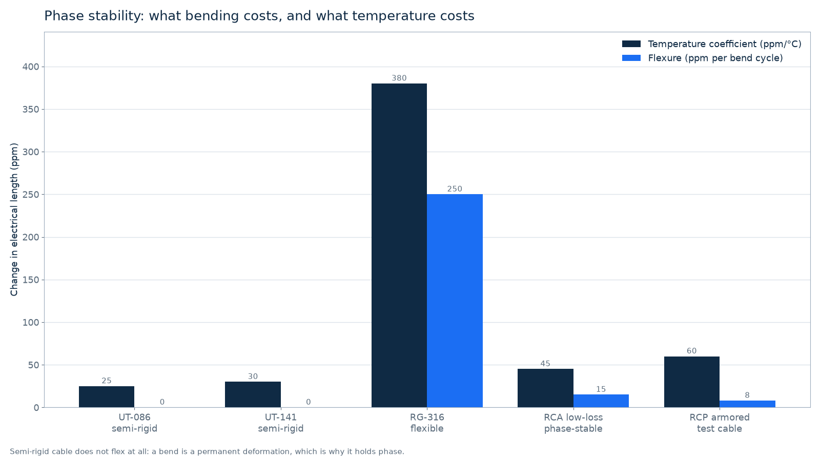
The unit makes it easy to underestimate. A coefficient of 300 ppm/°C sounds tiny until it is applied to a real run at a real frequency. One metre of PTFE-dielectric cable carries about 4.8 ns of delay, which is roughly 1,730° per GHz — so at 40 GHz that same metre is holding about 69,000° of phase, and 300 ppm/°C works out to 21° of drift per °C. A bench that swings 5 °C over an afternoon moves the reference plane by roughly 100° at 40 GHz. That is not a temperature coefficient problem any more; it is a calibration that expired without telling you.
The practical consequences are simple:
- Keep test cables short. Phase drift is proportional to length. A 60 cm test lead drifts 40 % less than a 1 m one, and the loss comes down with it.
- Clamp them, do not drape them. Every time a cable is picked up and put down, its electrical length changes a little. Taping the test leads to the bench in one position removes an entire class of “the measurement moved and I don’t know why”.
- Let the setup settle. After a calibration, give the cables and the DUT ten minutes to reach the same temperature as the room before trusting a 0.05 dB comparison.
- Re-calibrate when the bench moves. Not on a timer — on evidence. If a thru measurement has drifted, the reference plane has moved.
The Junction Is Where Assemblies Fail
Almost every cable assembly problem that shows up as a reflection happens at one of the two ends, not in the middle of the cable. The transition from a 0.9 mm centre conductor to a 0.29 mm one is a mechanical discontinuity that has to be compensated by the connector’s internal geometry, and the compensation only works if the assembly was built to the right dimensions for that cable.
This is why a connector is not a commodity part that can be crimped onto any cable of roughly the right diameter. Three specific things go wrong:
- Solder versus crimp. Solder gives a more repeatable electrical joint and is the norm for precision assemblies above 26 GHz; crimp is faster and fine for lower bands, but the crimp geometry has to match the cable’s dielectric and braid exactly.
- The pin depth. The centre pin has to sit within a few tens of micrometres of the mating plane. A pin that is 50 µm too far back creates a gap; one that protrudes damages the mating connector’s socket. Both are invisible and both cost return loss. This is the single most common defect in a re-terminated assembly.
- The bead and the back nut. The dielectric bead that supports the pin is what sets the impedance at the launch. Over-tightening the back nut distorts it, and the reflection appears at a distance from the connector that matches the bead’s position — you can see it in the sweep before you can see it on the bench.
For a 40 GHz assembly, buy the assembly rather than the parts. Re-terminating a .086 cable in-house is a reasonable exercise below 18 GHz and a source of slow, hard-to-find errors above it. The RCT test cable assemblies exist for that reason: the termination is done and tested as a unit, and the return loss is specified for the assembly rather than for the connector alone.
Matching the Cable to the Job
Four scenarios cover most of what a lab actually buys:
| Job | Right choice | Why not the cheaper option |
|---|---|---|
| VNA port extension to a DUT on the bench | Armored or low-loss phase-stable, 50–60 cm | A flexible cable that moves invalidates the calibration on contact |
| Permanent link inside an instrument or chassis | .086 or .141 semi-rigid, formed once | Flexible cable in a fixed run buys nothing and loses phase stability |
| Production test, high cycle count | Test-grade assembly with specified mating life | Bench cable wears out at the connector, not in the middle |
| DC, bias, control lines, low-band RF | RG-316 or similar flexible | Nothing — this is the case RG-316 was designed for |
If the run has to leave the bench and be coiled, dragged and re-laid every day, armor is not cosmetic: it fixes the bend radius, so the cable’s electrical length stops changing every time somebody moves it. That is the entire argument for armored assemblies in field and production work.
Length deserves the last word, because it is the parameter that is almost always chosen by convenience. Every extra 30 cm adds loss, adds phase drift, and adds one more place for the cable to move. If a 40 GHz measurement matters to two decimal places, measure how long the cable actually needs to be and then buy that length, rather than buying a 1 m assembly and coiling the excess behind the instrument.
FAQ
Is semi-rigid cable always lower loss than flexible cable?
No. A .141 semi-rigid and a good low-loss phase-stable flexible assembly land within a few tenths of a decibel at 40 GHz. Semi-rigid wins on phase stability because it cannot move; it does not automatically win on attenuation, and it loses badly on serviceability.
Can I use RG-316 at 26.5 GHz?
You can make a connection with it, and the loss will be tolerable for a short run, but you should not expect stable phase or a repeatable return loss. RG-316 is a general-purpose cable with a solid PTFE dielectric; its temperature and flexure coefficients are an order of magnitude worse than a phase-stable assembly, which means the calibration will not survive the afternoon.
Why does my calibration go stale when nobody touches the setup?
Almost always temperature. The reference plane is at the end of the test cable, and the cable’s electrical length changes with temperature at tens to hundreds of ppm per °C. Over a 5 °C swing that is enough to move the phase by more than a hundred degrees at 40 GHz. Clamp the cables, shorten them, and let the bench stabilise before comparing small numbers.
How tight should the connectors on a cable assembly be?
To the torque specified for the interface, with the right wrench: 0.9 N·m for SMA, 2.92 mm and 3.5 mm, 0.57 N·m for 1.85 mm, 0.45 N·m for 1.0 mm. Finger-tight is not tight enough at millimetre-wave frequencies, and a wrench borrowed from a different interface family is how connectors get destroyed. Our 1.0 mm care guide covers the torque and cleaning procedure in detail.
Does cable length affect VSWR?
It changes what you measure rather than how good the cable is. A fixed reflection at the far connector appears as a ripple whose period shortens as the cable gets longer, so a long cable spreads the same defect across more of the sweep and makes it look like a worse match. Judge an assembly on its specified return loss, and treat length as a contributor to ripple spacing.
The Short Version
Choose a cable assembly by its loss at the top of the band, its phase stability, its return loss repeatability and its bend radius — in that order — and only then by connector combination. Above 18 GHz the cable is the largest error source in the setup, and the two ways it fails are a reference plane that moves with temperature and handling, and a connector-cable junction that was never built to the frequency. Buy short, clamp what you buy, and replace assemblies on measurement evidence rather than on age.
For the connector end of the problem, the interface comparison guide explains which families mate and which only look alike; the VSWR and insertion loss primer covers how to read the sweep once the assembly is on the bench. Or send us the frequency, the length and the routing, and we will tell you which of the five families fits.
About the author — this guide is maintained by the RFSPECT engineering team in Shenzhen, who build coaxial adapters, attenuators, terminations and cable assemblies to 110 GHz. If a number here disagrees with the drawing you received, tell us and we will correct it.
Terms used above — phase stability, reference plane, return loss — are defined in the RF and microwave glossary.